Extension Cord Gauge Chart
Cord ampacity and computed voltage drop for 18 AWG through 10 AWG, at 25, 50, and 100 ft on a 120 V circuit.
5 A load (600 W on 120 V)
| Cord gauge | Rated for | 25 ft | 50 ft | 100 ft |
|---|---|---|---|---|
| 18 AWG | 10 A | 2 V · 1.7% under 3% at 120 V | 4 V · 3.3% over 3%, under 5% at 120 V | 8 V · 6.6% over 5% at 120 V |
| 16 AWG | 13 A | 1.2 V · 1% under 3% at 120 V | 2.5 V · 2.1% under 3% at 120 V | 5 V · 4.2% over 3%, under 5% at 120 V |
| 14 AWG | 18 A | 0.8 V · 0.7% under 3% at 120 V | 1.6 V · 1.3% under 3% at 120 V | 3.1 V · 2.6% under 3% at 120 V |
| 12 AWG | 25 A | 0.5 V · 0.4% under 3% at 120 V | 1 V · 0.8% under 3% at 120 V | 2 V · 1.7% under 3% at 120 V |
| 10 AWG | 30 A | 0.3 V · 0.3% under 3% at 120 V | 0.6 V · 0.5% under 3% at 120 V | 1.2 V · 1% under 3% at 120 V |
10 A load (1,200 W on 120 V)
| Cord gauge | Rated for | 25 ft | 50 ft | 100 ft |
|---|---|---|---|---|
| 18 AWG | 10 A | 4 V · 3.3% over 3%, under 5% at 120 V | 8 V · 6.6% over 5% at 120 V | 15.9 V · 13.3% over 5% at 120 V |
| 16 AWG | 13 A | 2.5 V · 2.1% under 3% at 120 V | 5 V · 4.2% over 3%, under 5% at 120 V | 10 V · 8.3% over 5% at 120 V |
| 14 AWG | 18 A | 1.6 V · 1.3% under 3% at 120 V | 3.1 V · 2.6% under 3% at 120 V | 6.3 V · 5.2% over 5% at 120 V |
| 12 AWG | 25 A | 1 V · 0.8% under 3% at 120 V | 2 V · 1.7% under 3% at 120 V | 4 V · 3.3% over 3%, under 5% at 120 V |
| 10 AWG | 30 A | 0.6 V · 0.5% under 3% at 120 V | 1.2 V · 1% under 3% at 120 V | 2.5 V · 2.1% under 3% at 120 V |
15 A load (1,800 W on 120 V)
| Cord gauge | Rated for | 25 ft | 50 ft | 100 ft |
|---|---|---|---|---|
| 18 AWG | 10 A | 6 V · 5% over cord ampacity — this cord cannot carry the load at any length | 11.9 V · 9.9% over cord ampacity — this cord cannot carry the load at any length | 23.9 V · 19.9% over cord ampacity — this cord cannot carry the load at any length |
| 16 AWG | 13 A | 3.7 V · 3.1% over cord ampacity — this cord cannot carry the load at any length | 7.5 V · 6.2% over cord ampacity — this cord cannot carry the load at any length | 15 V · 12.5% over cord ampacity — this cord cannot carry the load at any length |
| 14 AWG | 18 A | 2.4 V · 2% under 3% at 120 V | 4.7 V · 3.9% over 3%, under 5% at 120 V | 9.4 V · 7.9% over 5% at 120 V |
| 12 AWG | 25 A | 1.5 V · 1.2% under 3% at 120 V | 3 V · 2.5% under 3% at 120 V | 5.9 V · 5% over 3%, under 5% at 120 V |
| 10 AWG | 30 A | 0.9 V · 0.8% under 3% at 120 V | 1.9 V · 1.5% under 3% at 120 V | 3.7 V · 3.1% over 3%, under 5% at 120 V |
20 A load (2,400 W on 120 V)
| Cord gauge | Rated for | 25 ft | 50 ft | 100 ft |
|---|---|---|---|---|
| 18 AWG | 10 A | 8 V · 6.6% over cord ampacity — this cord cannot carry the load at any length | 15.9 V · 13.3% over cord ampacity — this cord cannot carry the load at any length | 31.8 V · 26.5% over cord ampacity — this cord cannot carry the load at any length |
| 16 AWG | 13 A | 5 V · 4.2% over cord ampacity — this cord cannot carry the load at any length | 10 V · 8.3% over cord ampacity — this cord cannot carry the load at any length | 20 V · 16.6% over cord ampacity — this cord cannot carry the load at any length |
| 14 AWG | 18 A | 3.1 V · 2.6% over cord ampacity — this cord cannot carry the load at any length | 6.3 V · 5.2% over cord ampacity — this cord cannot carry the load at any length | 12.6 V · 10.5% over cord ampacity — this cord cannot carry the load at any length |
| 12 AWG | 25 A | 2 V · 1.7% under 3% at 120 V | 4 V · 3.3% over 3%, under 5% at 120 V | 7.9 V · 6.6% over 5% at 120 V |
| 10 AWG | 30 A | 1.2 V · 1% under 3% at 120 V | 2.5 V · 2.1% under 3% at 120 V | 5 V · 4.1% over 3%, under 5% at 120 V |
Have a load and length in hand? Run it through the extension cord gauge helper.

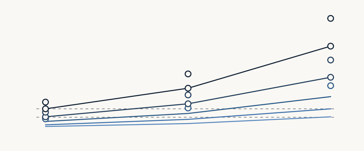
Thinnest gauge that holds the target
The thinnest cord on this ladder that stays inside the current ceiling and keeps drop at or under the guidance figure — arithmetic, not a listing.
| Length | Load | Thinnest under 3% | Thinnest under 5% |
|---|---|---|---|
| 25 ft | 5 A | 18 AWG | 18 AWG |
| 25 ft | 10 A | 16 AWG | 18 AWG |
| 25 ft | 15 A | 14 AWG | 14 AWG |
| 25 ft | 20 A | 12 AWG | 12 AWG |
| 50 ft | 5 A | 16 AWG | 18 AWG |
| 50 ft | 10 A | 14 AWG | 16 AWG |
| 50 ft | 15 A | 12 AWG | 14 AWG |
| 50 ft | 20 A | 10 AWG | 12 AWG |
| 100 ft | 5 A | 14 AWG | 16 AWG |
| 100 ft | 10 A | 10 AWG | 12 AWG |
| 100 ft | 15 A | No gauge on this ladder stays under 3% at 100 ft | 12 AWG |
| 100 ft | 20 A | No gauge on this ladder stays under 3% at 100 ft | 10 AWG |
Gauge reference
| AWG | Area (mm²) | Solid dia. (in) | Stranded dia. (in) | DC resistance (Ω/kft @ 75 °C) | Cord rating, 2 hot |
|---|---|---|---|---|---|
| 18 AWG | 0.823 | 0.0403 | 0.046 | 7.95 | 10 A (1,200 W) |
| 16 AWG | 1.31 | 0.0508 | 0.057 | 4.99 | 13 A (1,560 W) |
| 14 AWG | 2.08 | 0.0641 | 0.073 | 3.14 | 18 A (2,160 W) |
| 12 AWG | 3.31 | 0.0808 | 0.091 | 1.98 | 25 A (3,000 W) |
| 10 AWG | 5.26 | 0.1019 | 0.116 | 1.24 | 30 A (3,600 W) |
Two diameter columns because they are different things. Solid is equivalent solid round wire per ASTM B258-18. Stranded is the real 7-strand cord conductor, which measures about 12-14% larger because of the gaps between strands.
Why 12 AWG shows two different numbers on this site
The same size of copper can carry two different amounts of current, and both numbers can be right. What changes is what the wire is, and where it is allowed to go.
The wire ampacity chart is about building wire — THHN through conduit, or NM-B buried in a wall. That wire is sized from NEC Table 310.16, and its rating depends on the temperature of the terminals it lands on: 12 AWG copper is 20 A at 60 °C, 25 A at 75 °C, 30 A at 90 °C. Permanent house wiring usually lands on 20 A, because most receptacles and breakers are 60 °C rated.
This page is about flexible cord — the SJTW or SJEO type you uncoil for a saw or a shop light. Cord sits in a different part of the code, Article 400, and a different table, Table 400.5(A)(1), because a cord is a finished product that gets flexed, dragged, and used wet, and it is rated as a whole rather than sized on site. A normal three-conductor cord has two current-carrying conductors — two hots plus a ground — so it takes the two-conductor column: 12 AWG cord is rated 25 A.
So 20 A is the building-wire number for 12 AWG at 60 °C, and 25 A is the flexible-cord number for 12 AWG. Neither is a limit you get to pick between. Use the building-wire number when sizing permanent circuit wiring; use the cord number when choosing a cord to buy. At 10 AWG the two tables happen to agree at 30 A, and at 18 and 16 AWG the building-wire table has no row at all — which is most of why cords are their own subject.
One clarification, because the two tables get confused: 310.16 is not what sets either current figure. NEC 210.19(A) is the branch-circuit sizing rule, and its own Informational Note No. 1 says "See 310.15 for ampacity ratings of conductors." The ampacity comes from the conductor table — 310.16 for building wire, 400.5(A)(1) for cord. The 3% and 5% drop figures are a different note, 210.19(A) Informational Note No. 4, and are the same guidance on both pages. Where a chart and the cord jacket disagree, the jacket is what that cord was certified as.
How to read this chart
Pick the load first — the four tables above are one per load, with jumps at the top of the page. Then find your cord's gauge in the left column and move across to your length. The number in that cell is the volts lost reaching the load and the share of supply voltage that accounts for, both computed for a 120 V circuit at hot-conductor resistance. Read the sentence under it: "under 3%" clears the tighter guidance figure, "over 3%, under 5%" clears only the looser one, "over 5%" clears neither.
A shaded cell is not missing data. It marks a combination where the load is above the cord's current ceiling, so no length of that cord carries the load — the rating is the limit, not the distance. The fix is a heavier gauge, not a longer cord.
Where these numbers come from
Current figures come from NEC Article 400, Table 400.5(A)(1), cross-checked against a manufacturer cord table that agrees on every value here. Conductors are stranded, so resistance and diameter come from the 7-strand rows of NEC Chapter 9 Table 8, and drop is computed on the round trip: out on the hot, back on the neutral.
What this chart does not decide
A 120 V reference for finished flexible cord. It does not size permanent circuit wiring, and it does not pick a product — it publishes the ceiling a cord carries and the drop it costs. Every cell is arithmetic on a published resistance table, not a measurement of your cord.
Reference only — not a wiring design tool. AC impedance / reactance, temperature correction, conductor ampacity derating, 240 V. Out of scope for a 120 V retail cord page.
No product recommendation and no purchase link appear here: the size families sold as loose building-wire spools are a different product from the flexible cord this page measures. Read the marking on the cord itself as the governing figure, and check anything permanent against local code with a qualified electrician.
Extension cord gauge questions
Which is thicker, 12 gauge or 14 gauge, and what can each carry?
14 AWG is the thicker conductor. On this chart 14 AWG is rated 18 A and 12 AWG is rated 25 A, a jump of 39%. You can see it in the copper too: a 12 AWG cord conductor measures about 0.091 in across and a 14 AWG about 0.073 in. Those are the ratings the cord carries — the size and rating moulded into the jacket are the ones that govern.
How long can a 12 AWG extension cord be?
Length is limited by voltage drop, not by the current ceiling, and the drop grows with distance. 10 A runs to 0.8% at 25 ft and 1.7% at 50 ft, then crosses the 3% guidance at 100 ft, at 3.3%. At 15 A, 50 ft is 2.5% and 100 ft is 5%. For a long run, step up a gauge instead of adding length.
Why does 12 AWG show 25 A here but 20 A on the ampacity chart?
Different questions, two different code tables, both correct. The ampacity chart is building wire sized from NEC Table 310.16, where 12 AWG is 20 A at 60 °C terminals. This page is flexible cord, sized from NEC Article 400 Table 400.5(A)(1), where 12 AWG is 25 A. The section above covers the difference in full.
How do I find out what gauge my extension cord is?
Read the jacket. The size, voltage rating and temperature rating are moulded into the cord's outer insulation and repeated on the tag. If that printing has worn away, treat the gauge as unknown and replace the cord rather than guessing — an unmarked cord cannot be checked against this chart or anything else.
What does the wattage rating on a tool mean for cord length?
Divide the tool's watts by 120 for its draw in amps: 600 W is about 5 A, 1,200 W is about 10 A, 1,800 W is about 15 A, 2,400 W is about 20 A on a 120 V circuit. Motors are the exception: the nameplate is running current and startup surge runs several times that, so a saw or grinder wants headroom above its plate.
Sources
- NFPA 70 National Electrical Code 2017, Article 400, Table 400.5(A)(1) — Allowable Ampacity for Flexible Cords and Flexible Cables (30 C ambient) — National Fire Protection Association, 2017 edition.
- NFPA 70 National Electrical Code 2017, Chapter 9, Table 8 — Conductor Properties (Direct-Current Resistance at 75 C, uncoated copper, 7-strand rows) — National Fire Protection Association, 2017 edition.
- NFPA 70 National Electrical Code 2017, 210.19(A)(1) Informational Note No. 4 (and 215.2(A)(1) Informational Note No. 2) — voltage-drop guidance — National Fire Protection Association, 2017 edition.
- Southwire 300V SEOPRENE SJEOOW Flexible Cord, SPEC 70065 — allowable ampacity and conductor resistance table — Southwire Company, LLC, retrieved 2026-10-05 (no publication date printed).
- ASTM B258-18 Standard Specification for Standard Nominal Diameters and Cross-Sectional Areas of AWG Sizes of Solid Round Wires Used as Electrical Conductors — ASTM International, 2018.
Computed cells follow E = 2 x I x R x L (loop: current out on the hot, back on the neutral), resistance from sources[1] ohm/kft at 75 c, 7-strand uncoated copper. Rounding: loop_ohms to 2 dp, volts_drop and drop_pct to 1 dp.
Related wire references
- Wire hub
- Extension cord gauge helper — enter a load and length for a suggested gauge class.
- Wire ampacity chart — the building-wire side of the 12 AWG comparison above.
- Wire gauge chart — AWG diameters and bare-conductor dimensions.
- What gauge wire for 20 amp
- Wire color code chart